Demonstrating the Automatic Tank Dewatering and Desalting Sensor
Prevention is better than the cure.
The ID200h is the first and only interface control system to utilize this understanding of the oil/water interface as the basis for control. The system consists of a minimum of two or a maximum of four Agar energy absorption instruments: three designated for service in the vessel and one installed upstream of the unit in the crude feed line. In the System 3 control scheme, this sensor provide continuous 4 to 20 mA output signals proportional to the % water concentrations at their locations inside the desalter.
ID200h Series Enhanced Connectivity and Power Efficiency
Sensor features
The ID200h Series stands out with its 2 Wire loop-powered system and HART communication protocol, offering seamless integration and enhanced energy efficiency. It is ideal for sophisticated control systems requiring advanced communication capabilities.
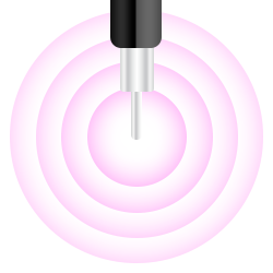
A hight-frequency, low-power energy is broadcast.

The detection range is a 3″ sphere around the tip.
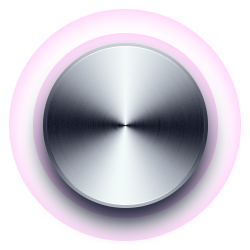
Some of the energy is absorbed by the medium surrounding the antenna.

The analogue signal is generated relative to the absorption rate.
Trusted by some of the best in the industry

Unique 4-phase technology
Our innovative 4-phase technology, designed to optimize the removal of water, oil, gas, and solids from your process streams. This advanced system ensures precise interface detection and control, reducing contamination and enhancing overall performance.
Saving you millions
By installing ID-200 Interface Detectors, a US refinery reduced its total HC being dumped to the WWTS by 82% with better interface/separation control. An 82% reduction in SLOP OIL generated equals £1,990,424 per year in savings/additional profit. Not just for the first single year but continuing year after year.
82% reduction in slop oil waste
Unique 4-phase system
What are the four methods of dewatering?
This section will guide you through each phase, illustrating how the ID200h seamlessly transitions and adapts to varying process conditions. The ID200h demonstrates unparalleled accuracy and efficiency in each stage, from initial detection to precise control.
Phase 1
The first phase controls the brine outlet valve – using its ability to measure small amounts of oil in water to maintain a very high (and unstable) percentage of water several feet above the bottom of the vessel. This allows suspended oil in the water phase to separate, thus inhibiting oil undercarry as a primary control function. While sensor #1 establishes this lower limit for the emulsion layer, anything that floats on the water phase stops here.
Phase 2
Monitors the % water content from its position in the oil phase just below the lower grid. This provides real-time detection of the rate and extent of emulsion growth (which must, by sensor #1’s control, occur in the upward direction). Sensor #2’s monitoring function allows the operator to avoid downstream upsets by providing advanced warning of such growth and allows time to implement corrective measures to prevent grid loss (transformer “trip”).
Phase 3
Monitors the % water content from its position in the oil phase just below the lower grid. This provides real-time detection of the rate and extent of emulsion growth (which must, by sensor #1’s control, occur in the upward direction). Sensor #2’s monitoring function allows the operator to avoid downstream upsets by providing advanced warning of such growth and allows time to implement corrective measures to prevent grid loss (transformer “trip”).
Phase 4
The fourth sensor monitors the condition of the water phase below the control sensor, alarming the presence of suspended oil that does not readily separate and threatens the condition of the brine effluent. This is of particular value when low-quality sources of wash water (e.g. stripped or straight sour water) are utilised that can upset the separation process and form stable oil-in-water mixtures (reverse emulsions). This is also used during mud-wash cycles.
Demonstrating the functions of the ID200h
Installation of the ID200
Your questions answered.
Your questions answered about tank dewatering.
How can tanks be dewatered?
Oil tanks can be dewatered using several methods, but one of the most effective is interface detectors like the ID-200. These devices precisely measure and control the separation of liquids, allowing for the efficient removal of water from various substances. Other methods include centrifugation, filtration, and using absorbent materials, each suitable for different types of tanks and contents.
What does a dewatering tank do?
A dewatering tank separates water from other materials, such as sludge, oil, or other industrial fluids. The primary function is to reduce the volume of the material by removing the water content, making the remaining substance easier to handle, process, or dispose of. This process is essential in many industries, including wastewater treatment, oil refining, and chemical processing.
What happens to dewatered sludge?
Dewatered sludge, the solid material left after water removal, can be processed in several ways. It is often treated further to reduce contaminants and then repurposed or disposed of safely. Common uses for treated sludge include agricultural fertilizers, landfill cover, or as a fuel source in incineration processes. The method of disposal or repurposing depends on the sludge’s composition and level of treatment.
What is the most effective dewatering system?
The effectiveness of a dewatering system depends on the application’s specific requirements. However, systems incorporating advanced interface detectors like the ID200 are often considered the most effective. These systems offer precise control, high efficiency, and adaptability to various industrial needs. Other effective systems include belt filter presses, centrifuges, and screw presses, each having its advantages depending on the material being processed and the desired outcome.
A lasting collaboration
Looking after your world since 1971
Knowledgeable, experienced staff
Our team of dedicated field support group technicians are vastly experienced in applications and installations. We therefore appreciate and understand how analysers work, why they were installed and what data they typically ought to produce.
Spare and replacement parts
Scroll down to use our contact form to enquire about spare and replacement parts. If you do not know the part number or name for a required spare part please simply describe the spare part. Our team of expert engineers are here to help.
Requesting technical documents
Submit your details at the bottom of this page and your request will be processed immediately by our team of engineers at PMA. For technical documents please ensure to include details about your application so that our team can deliver a bespoke document for your specific requirements.
All great relationships start with a conversation
To contact us, or to request a callback, simply use this form and we will promptly get back to you.